The gap between “I have a thermal imaging module” and “I have a working drone payload” is wider than most first-time payload designers expect. This guide covers the full integration path, drawing on common issues we see when customers bring us their designs for engineering review.

Phase 1: Define the Mission Profile First
Before touching hardware, lock down the mission profile:
- Aircraft type and mass budget: What is the total payload mass the aircraft supports? A 250 g budget eliminates cooled MWIR entirely.
- Flight time requirement: Thermal payload power directly reduces endurance. A 5 W payload on a 30-minute aircraft costs roughly 2–3 minutes of flight time.
- Detection range: This determines minimum detector format and focal length, which drives gimbal volume.
- Video transmission: Are you using the aircraft’s existing data link? What bandwidth and latency does it provide?
- Operating environment: Temperature extremes, humidity, and altitude affect module selection and enclosure design.
Phase 2: Mechanical Design
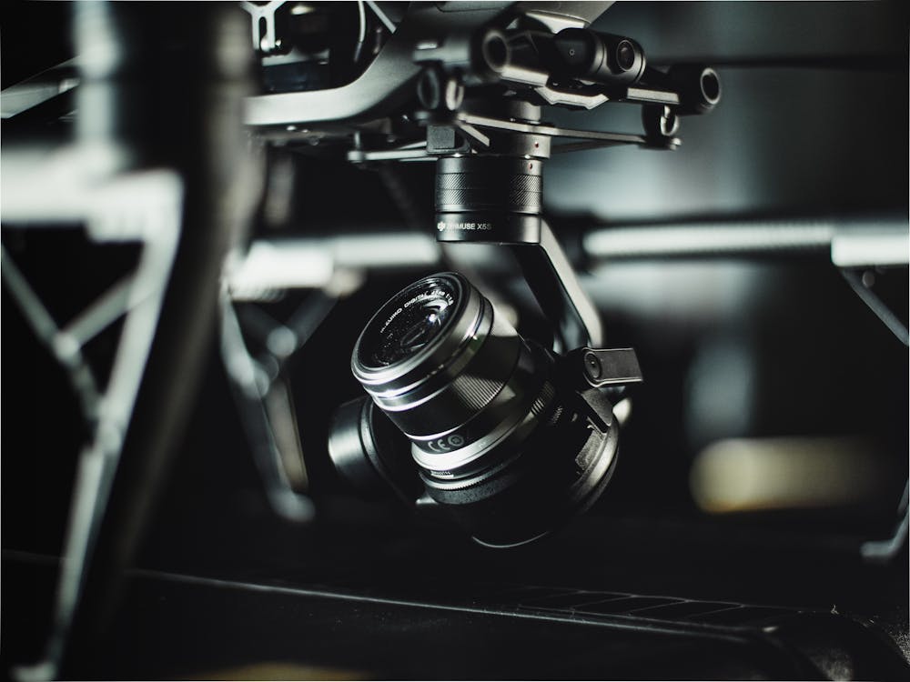
The 35×35 mm module footprint used by IRmodules’ SPECTRA and FUSION series is the industry standard for compact drone payloads, but “fits on a 35 mm mount” is not the same as “integrated correctly.”
Common mechanical errors:
- PCB flexure during vibration: Secure modules through their threaded bosses, not PCB perimeter clips. Rotorcraft generate sustained 50–200 Hz vibration profiles that can induce flex-mode resonance in a PCB-mounted sensor.
- Lens protrusion planning: Account for the lens assembly extending beyond the module PCB. Many designs discover interference between the lens and the gimbal housing during first assembly.
- NUC shutter clearance: Uncooled LWIR modules use an internal shutter for NUC correction. The shutter mechanism requires 0.5–1.0 mm clearance from adjacent structures in the z-axis direction. Check this early.
Phase 3: Electrical Integration
Power
Provide module power from a dedicated filtered regulator, not directly from the aircraft bus. ESC switching noise and motor drive interference are substantial on most multirotors.
Recommended filter for SPECTRA L06/L12:
- Input: LC filter (10 μH, 100 μF X7R ceramic)
- Output bulk capacitance: 220 μF electrolytic + 10 μF ceramic at module connector
Isolation
For gimbals where the module PCB rotates relative to the aircraft, use quality flex cables with bend radius ≥ 20 mm and minimize cable tension through the rotation travel. MIPI CSI-2 cables are particularly susceptible to signal integrity degradation when kinked.
Phase 4: Software and Video Pipeline
| Component | Typical Choice | Notes |
|---|---|---|
| On-payload processor | NVIDIA Jetson Orin Nano, Qualcomm RB5 | Must have MIPI CSI lanes matching module output |
| Video encoder | H.265 hardware encoder on SoC | 1280×1024 @ 30 fps requires ~4 Mbps at acceptable quality |
| Ground link | MAVLink/video over UDP | Ensure sufficient bandwidth for thermal + visible streams |
| NUC management | Software-triggered via UART | Prevent NUC during critical recording windows |
| Metadata overlay | GPS coordinates, timestamp, range | Encode in SEI NAL units or side-channel |
For AI-enabled payloads, the NEXUS LV0619B eliminates a separate AI processor — target detection and tracking run at the module level, and only detection results (bounding boxes, classifications) need to be transmitted over the data link, dramatically reducing bandwidth requirements.
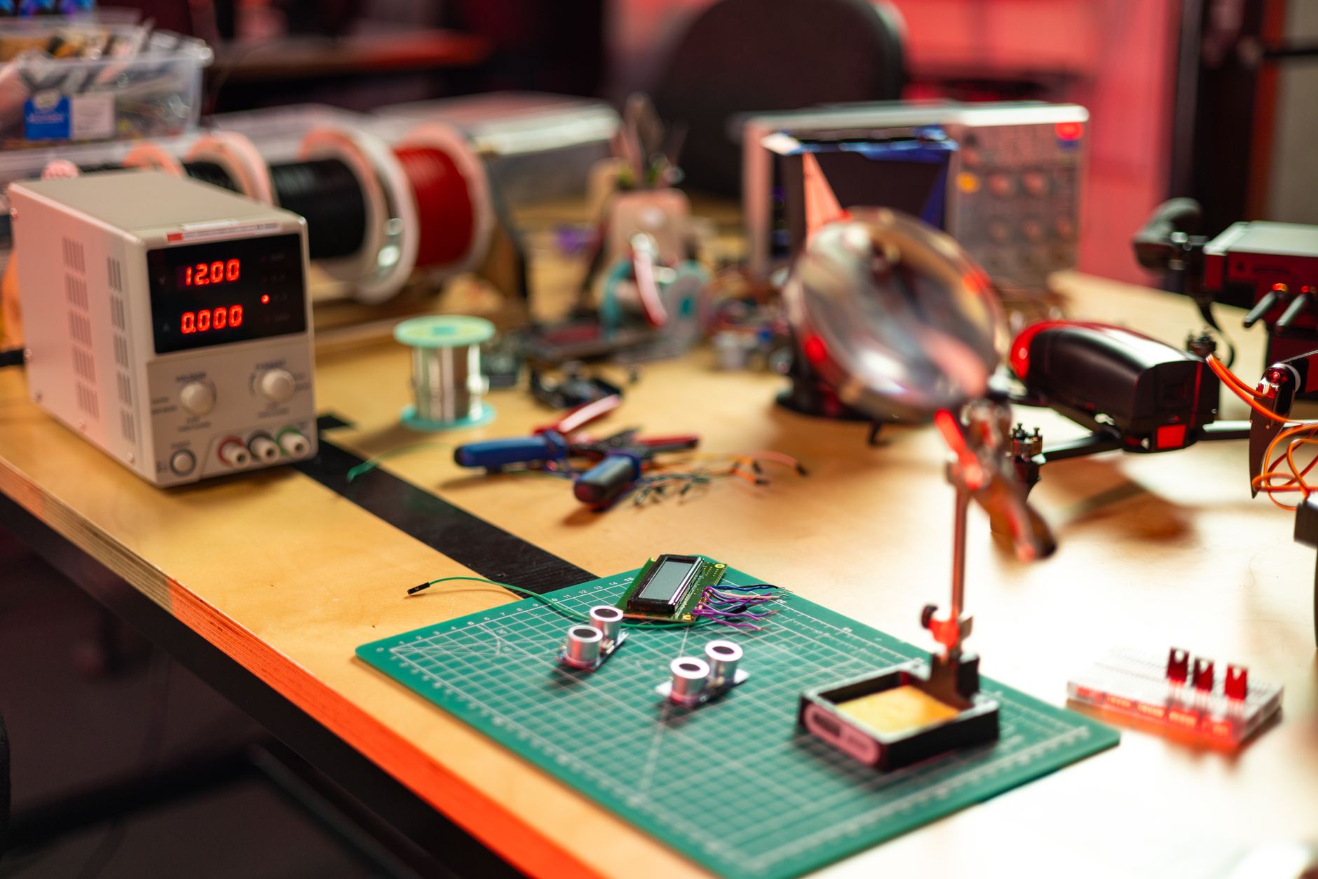
Phase 5: Testing Before First Flight
Never fly a new thermal payload without bench validation of these items:
- Full temperature range test: Power cycle and operate the payload across its stated operating temperature range. Thermal cameras are sensitive to ambient temperature changes — verify image stability across the range.
- Vibration characterization: Mount the payload on a representative vibration fixture (or clamp to a running motor) and observe image quality. Look for resonance modes that degrade MTF or trigger false NUC events.
- EMI validation: Operate motors and ESCs simultaneously with the payload. RF interference from motor drive waveforms is a common source of image artifacts that only appear in actual flight configuration.
- Endurance soak: Run the complete payload at maximum power for 2× the expected flight duration. Heat builds up differently in flight (airflow varies) than on the bench.
UAV payload design is iterative — plan for at least two hardware revisions before reaching production-ready design. IRmodules can support early-stage electrical design review and provide module application notes tailored to common UAV SoC platforms.