A gimbal is only as capable as the imaging cores inside it. You can have perfect stabilization, whisper-quiet motors, and a 360° slew rate — but if the sensors don’t provide the image quality the mission requires, the mechanical excellence is wasted. This article focuses on what the imaging module selection decision looks like from a gimbal system designer’s perspective.
Start With the Platform, Not the Module
Before opening a datasheet, define the constraints your platform imposes:
- Mass envelope: What is the gimbal’s total mass budget? Typical payload-class UAV gimbals run 150–800 g.
- Power budget: What sustained power can the aircraft supply to the gimbal? This affects whether cooled (high power) modules are viable.
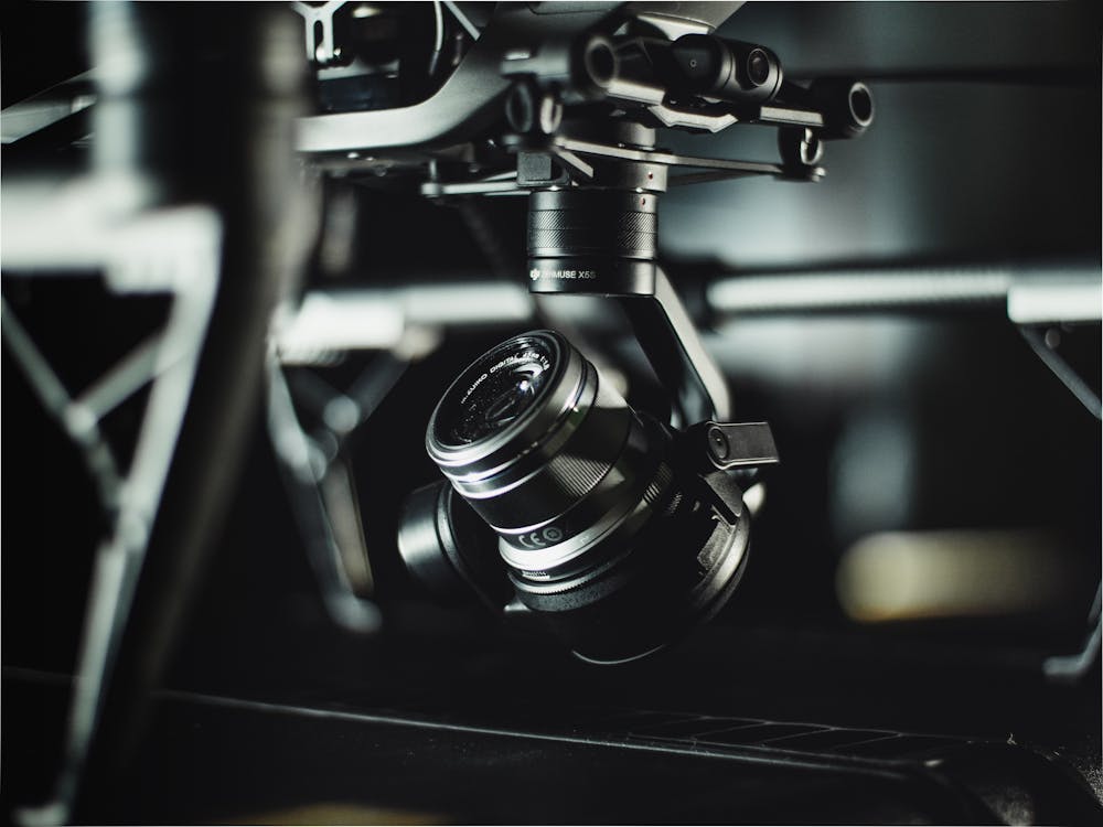
- Volume envelope: What are the outer dimensions of the gimbal head? 35 mm pitch mounting is the de facto standard for compact modules.
- Interface to aircraft: Ethernet, USB 3.0, SDI, or proprietary? This influences whether on-gimbal processing is needed.
The SWaP Equation for Gimbal Modules
For small gimbal systems (sub-500 g), uncooled LWIR is almost always the right thermal choice. Cooled MWIR modules add 150–400 g for the Stirling cooler assembly alone, plus 10–25 W of additional power draw, plus cooldown time. The improved NETD (20 mK vs 50 mK) often doesn’t justify this in a UAV context where the dominant range limitation is optics, not sensitivity.
For larger gimbals (500 g – 2 kg, military-class), the calculus changes. At ranges beyond 3–5 km, cooled MWIR’s superior long-range sensitivity and atmospheric transmission in humid environments become decisive. The SPECTRA H10 (cooled MCT, MWIR 1024×768) is the core of choice for this class.
Single-Sensor vs Dual-Band
The trend in modern gimbals is toward dual-band — simultaneous infrared and visible imaging from a single module. The advantages compound quickly:
- Single optical axis: no boresight registration between channels required
- Single power connection: one module instead of two separate units
- Fusion output: on-module pixel-aligned thermal+visible enables AI algorithms to combine channels
The FUSION LV0625A provides 640×512 LWIR + 1280×960 visible in a 35×35 mm package at DC 5V. The higher-resolution FUSION LV1225A delivers 1280×1024 LWIR + 2560×1440 visible for longer-range applications.
Single-band thermal with a separate visible camera remains valid when you need independent zoom ratios between channels, or when the visible module needs to be larger format than a dual-band module provides.
Mechanical Integration Considerations
| Constraint | Solution |
|---|---|
| Vibration (rotorcraft) | Use module’s threaded mounting bosses, not PCB flex |
| Thermal gradient across gimbal head | Mount module against gimbal frame for thermal mass coupling |
| Cable routing through gimbal rotation | Use slip ring or flex cable with minimum bend radius > 20 mm |
| Optical axis alignment | Reference to module’s mechanical datum, not PCB edge |
The SPECTRA and FUSION series modules use M2 mounting bosses at defined reference positions, enabling repeatable boresight alignment across production units.
Interface Architecture for Gimbals
Most compact gimbals process video on-gimbal and transmit compressed video to the aircraft. This means you need:
- Module → on-gimbal processor: MIPI CSI-2 (short distance, < 300 mm) or CML LVDS (up to 2 m)
- On-gimbal processor → aircraft: H.264/H.265 encoded video over Ethernet, or SDI for low-latency applications
For AI-enabled gimbals, the NEXUS LV0619B with onboard NPU eliminates the need for a separate AI accelerator board — target detection runs on the module itself, freeing the host processor for other tasks.
Checklist for Module Selection in Gimbal Applications
- Confirm module fits within gimbal head volume (35×35 mm footprint)
- Verify power draw is within gimbal power budget at worst-case temperature
- Select interface based on module-to-processor cable length and host SoC capability
- For dual-band: verify that single optical axis meets mission boresight requirements
- Confirm operating temperature range covers expected deployment environment
- Validate lens thread pitch compatibility with existing or planned optics
IRmodules supports gimbal OEMs with customized module configurations including modified output interfaces, alternate connector placements, and custom lens mounts. Contact our engineering team with your platform specification for a guided selection.