Thermal management for infrared camera modules is a system-level design task, not only a heat-sink selection step. Detector temperature, optics temperature, electronics power, enclosure conduction, airflow, and calibration strategy all influence image stability. In OEM integration, poor thermal design can appear as non-uniformity, focus shift, boresight drift, increased noise, shortened cooler life, or inconsistent radiometric output. The correct approach depends on detector type, operating environment, duty cycle, enclosure architecture, and whether the module is used for qualitative imaging, detection, or calibrated temperature measurement.
How Does Thermal Management for Infrared Camera Modules Work?
Infrared modules contain multiple temperature-sensitive elements. The detector converts incident radiation into an electrical signal, the readout integrated circuit conditions that signal, and image-processing electronics apply correction, enhancement, and output formatting. Heat is generated by the electronics, cooler drive circuitry, motors, communication interfaces, and sometimes by a thermoelectric cooler. Heat also enters the module through solar loading, nearby motors, sealed housings, vehicle structures, or high-temperature process equipment.
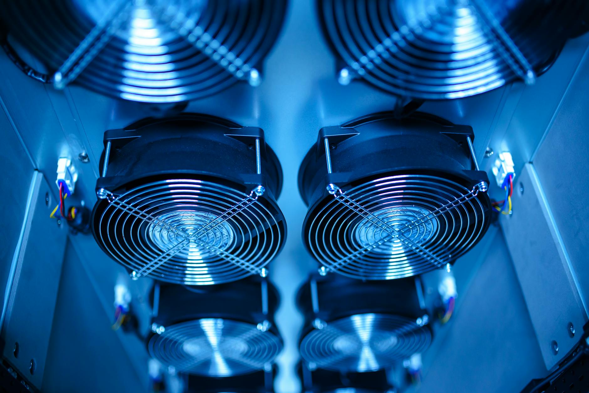
Thermal management works by defining predictable heat paths from these sources to the outside environment. In a conduction-cooled integration, the module case is clamped to a chassis, cold plate, gimbal frame, or heat spreader. In a passively cooled housing, the enclosure surface area and material properties determine heat rejection. In an actively cooled system, fans, liquid cooling, or thermoelectric devices may be added, but they introduce power, vibration, contamination, and reliability considerations.
The detector does not need to be the hottest component to be affected by heat. For uncooled LWIR microbolometers, detector substrate temperature changes can shift pixel offset and responsivity. SPIE’s overview of thermal detectors describes the basic principle: absorbed radiation changes detector temperature, and the detector structure must respond predictably to that change. In a camera module, that useful signal must be separated from package temperature drift, self-heating, and scene-independent thermal gradients.
Optics also matter. Lens barrels, mounts, windows, and focus mechanisms expand with temperature. A small focus shift can reduce modulation transfer at long range, while temperature gradients across the optical stack can affect boresight. For multi-sensor systems, visible, SWIR, MWIR, and LWIR channels may not drift equally, so mechanical and thermal coupling should be evaluated together.
What Thermal Parameters Matter Most in Infrared Camera Integration?
The most important parameter is allowable case temperature, because the OEM typically controls the surface or structure that receives heat from the module. Case temperature is not identical to ambient temperature. A sealed vehicle pod, UAV gimbal, or industrial enclosure can run much hotter than the surrounding air, especially under solar load or with nearby power electronics.
Thermal resistance is the next practical parameter. It defines how much temperature rise occurs per watt between a heat source and a reference point, usually from internal electronics to case or from case to ambient. A module drawing several watts in still air may be acceptable on a laboratory bench but unstable inside a sealed enclosure if the integration does not provide a conduction path.
Power consumption must be evaluated by operating mode. Standby, imaging, full-frame output, image processing, Ethernet transmission, TEC control, and cooler startup do not create the same heat load. Cooled MWIR modules are especially sensitive to peak power during cooldown. The steady-state power after the detector reaches setpoint may be much lower than the startup demand, but the host system must support both.
Temperature stability is different from absolute temperature. A module can operate within its specified temperature range and still require more frequent non-uniformity correction if its internal temperature is changing rapidly. For radiometric systems, stabilization time after power-on, hot soak, or cold start should be specified as part of the measurement budget.
Correction behavior should be reviewed with the module supplier. Flat-field correction, shutter-based NUC, shutterless correction, bad-pixel replacement, and gain/offset tables all interact with thermal state. NIST’s thermal camera calibration and measurement procedure is a useful reference for understanding why calibration, emissivity, optics, and uncertainty sources must be treated explicitly when the image is used for measurement rather than detection alone.
Cooled MWIR vs Uncooled LWIR: How Do Thermal Design Requirements Differ?
Uncooled LWIR modules generally use microbolometer focal plane arrays and operate near ambient temperature. They do not require a cryocooler, which reduces size, power, acoustic noise, and mechanical complexity. However, they still require thermal control at the module level. Temperature drift changes pixel behavior, which is why uncooled cameras rely heavily on calibration tables, detector temperature sensing, and NUC strategy. IEEE Xplore includes work on uncooled microbolometer FPAs without substrate temperature stabilization, illustrating the engineering focus on compensation when active stabilization is reduced or removed.
For compact OEM products, an uncooled module such as SPECTRA L06A 640×512 LWIR 12μm may be selected when size, power, and integration simplicity dominate. The host design should still provide a low-gradient mounting environment and avoid placing the module next to intermittent heat sources such as radios, processors, motor drivers, or battery packs.
Cooled MWIR modules use a cryogenic cooler and a Dewar assembly to hold the detector at a low operating temperature. This enables higher sensitivity and faster integration times in many MWIR applications, but the thermal problem shifts. The detector is cold, yet the cooler rejects heat into the surrounding structure. The OEM must manage cooler input power, heat rejection, vibration, cooldown time, and long-term cooler life.
A module such as SPECTRA M06A 640×512 Cooled MWIR 15μm requires a host structure that can absorb and reject the cooler’s waste heat without raising the module case beyond specification. For extended range or higher format cooled imaging, the thermal path becomes more important because optics, cooler drive electronics, and processing electronics all contribute heat. High-operating-temperature cooled designs, such as SPECTRA H10A 1024×768 HT-Cooled MWIR, can reduce cooling burden compared with lower-temperature detector operation, but they still require disciplined case-temperature control.
SWIR modules are different again. InGaAs sensors do not image thermal emission in the same way as LWIR or MWIR thermal cameras, but dark current, gain stability, and electronics noise remain temperature-dependent. For multi-band payloads, the SWIR channel may also need thermal alignment with MWIR or LWIR channels to preserve registration.
When to Use Active Cooling, Passive Heat Sinking, or Environmental Isolation
Passive conduction is usually the preferred first design choice when the host platform has a stable mechanical structure and a defined heat-rejection path. A machined aluminum chassis, gimbal frame, or vehicle bracket can act as a heat spreader if the interface is flat, clamped correctly, and designed with an appropriate thermal interface material. Passive designs avoid moving parts and simplify qualification.
Active cooling is appropriate when passive rejection cannot maintain the module case within limits across the full operating envelope. Fans can improve convection but may be unsuitable in sealed, dusty, wet, or high-altitude systems. Liquid cooling can support high heat loads but adds pumps, fittings, leak risk, and maintenance requirements. Thermoelectric coolers can stabilize a local surface, but they move heat rather than eliminate it, so the hot side must be designed carefully.
Environmental isolation is useful when the external temperature changes faster than the module can compensate. Insulation, sun shields, low-emissivity exterior finishes, window heaters, and controlled internal airflow can reduce gradients and transient drift. In outdoor applications, solar loading on one side of a housing can create larger image effects than uniform ambient temperature. For Airborne/UAV payloads, altitude, airspeed, solar exposure, and intermittent operation can create thermal cycles that are not visible in a room-temperature bench test.
The trade-off is response time. A heavily insulated module may be protected from fast external changes but can retain self-generated heat. A highly conductive mount may remove internal heat efficiently but transfer vehicle or enclosure temperature transients into the camera. The correct balance depends on whether the priority is rapid startup, long-duration stability, low power, compact packaging, or radiometric repeatability.
How to Validate Thermal Stability in an OEM Camera Module
Thermal validation should start with a realistic operating profile. A useful profile includes cold start, hot start, steady-state operation, frame-rate changes, output-interface load, shutter or calibration events, and environmental ramps. Testing only at room temperature does not reveal how the module behaves after a sealed enclosure reaches equilibrium or after the platform transitions from standby to full operation.
Measurements should include module case temperature, nearby host structure temperature, internal telemetry if available, power consumption, NUC interval, image non-uniformity, NETD, focus position, boresight, and any radiometric output error. For multi-sensor payloads, registration drift between channels should be measured over temperature. For cooled modules, cooldown time, cooler power, case temperature, and vibration sensitivity should be logged together.
Blackbody testing is important when the camera is used for measurement or threshold-based detection. Two-point or multi-point checks across the expected target temperature range can show whether calibration remains valid after thermal soak. EMVA’s EMVA 1288 framework is not a complete replacement for infrared-specific radiometric validation, but it is relevant for objective camera characterization, including noise and non-uniformity concepts that OEM teams should document consistently.
Thermal validation should also include the final enclosure. A module that passes chamber testing as a bare unit can fail in the product because the enclosure changes airflow, conduction, window temperature, and radiation exchange. Window heaters, conformal coatings, desiccants, sealing materials, and nearby processors may all change thermal behavior. The acceptance test should therefore include the mechanical stack, optics, electronics, firmware settings, and mission duty cycle.
For OEM selection, thermal management should be treated as a requirement alongside resolution, spectral band, interface, size, and image processing. The right infrared camera module is the one that meets sensitivity and image-quality targets while remaining thermally stable in the actual host platform, not only under datasheet conditions.
FAQ
How much heat sinking does an infrared camera module need?
The required heat sinking depends on module power, allowable case temperature, ambient conditions, enclosure design, and duty cycle. A practical calculation starts with worst-case power and maximum allowed temperature rise, then converts that into a required thermal resistance from module case to ambient or to the host structure. The result should be verified in the final enclosure because sealed housings and solar loading can change the effective heat path.
Does an uncooled LWIR camera module need temperature control?
Yes, but not necessarily active cooling. Uncooled LWIR modules often operate near ambient temperature, yet microbolometer response changes with detector and package temperature. Good integration provides a stable, low-gradient mounting environment and allows the module’s internal correction strategy to work predictably. Rapid temperature ramps or local hot spots can increase NUC frequency and reduce image consistency.
Why does a cooled MWIR module need thermal design if the detector is already cooled?
The cryocooler removes heat from the detector and rejects heat into the module body and host structure. If that rejected heat is not managed, the case temperature can rise, cooler efficiency can decrease, cooldown time can increase, and nearby optics or electronics can drift. Cooled MWIR integration therefore requires both cold-side performance and hot-side heat rejection to be considered together.
How does housing temperature affect infrared image stability?
Housing temperature affects the camera through conduction, radiation, and optical alignment. A warm or unevenly heated enclosure can raise module case temperature, create gradients across the lens, heat the window, and change mechanical alignment. These effects can appear as non-uniformity, apparent scene-temperature error, focus shift, or channel misregistration in multi-band systems.
What should OEM teams ask before selecting an infrared camera module?
OEM teams should ask for operating case-temperature limits, power by operating mode, startup and stabilization time, NUC behavior, cooler requirements if applicable, thermal-interface recommendations, and test data over the intended environment. These answers make it easier to compare LWIR, MWIR, SWIR, and multi-band modules against the actual mechanical, electrical, and thermal constraints of the product.